

PRODUCT CENTER
-
Frequency conversion series resonance complete device
-
High voltage withstand test equipment
-
Transformer testing equipment
-
Switch testing equipment
-
Transformer/electric energy metering and testing equipment
-
Relay protection/secondary circuit test equipment
-
Lightning arrester/insulator testing equipment
-
Grounding/Insulation Resistance Test Equipment
-
Cable and transmission line testing equipment
-
Generator and capacitor testing equipment
-
Safety equipment testing equipment
-
SF6 gas detection class
CONTACT US
Contact number:
13016458318 027-85821963
Company address:Room 01, 3 / F, building 4, daijiashan science and Technology City, 888 Hanhuang Road, Jiang'an District, Wuhan City
After-sale service:
18971110046
E-mail:

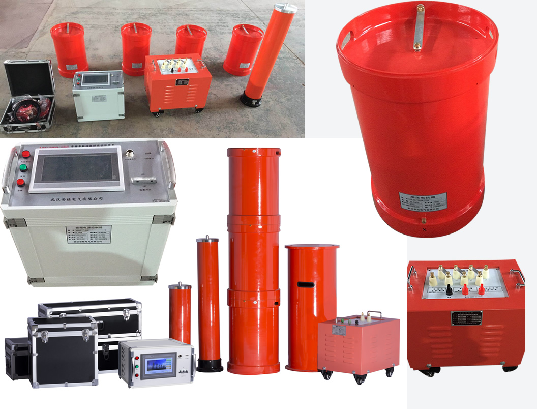
AJBX electrical equipment AC withstand voltage resonance test device
|
Serial number
|
Device name
|
Specification model
|
Unit
|
Quantity
|
|
1
|
Variable frequency power supply
|
AJBX-7.5kW
|
Station
|
1
|
|
2
|
Excitation transformer
|
JLB-7.5kVA/1.5/3/6kV/0.4kV
|
Station
|
1
|
|
3
|
High voltage reactor
|
DK-33.75kVA/27kV
|
Station
|
4
|
|
4
|
Capacitor voltage divider
|
FC-1000pF/110kV
|
Set
|
1
|
|
Rated voltage U0/U(kV)
|
Test voltage
|
Time (min)
|
|
18/30 and below
|
2.5U0(z or 2U0)
|
5(or 60)
|
|
21/35-64/110
|
2U0
|
60
|
|
127/220
|
1.7U0 (or 1.4U0)
|
60
|
|
190/330
|
1.7U0 (or 1.3U0)
|
60
|
|
290/550
|
1.7U0 (or 1.1U0)
|
60
|
|
Rated voltage U0/U(kV)
|
Test voltage
|
Time (min)
|
|
|
Newly commissioned lines or non-newly commissioned lines not more than 3 years old
|
Non-newly put into operation line
|
||
|
Below 18/30
|
2.5 U0(2U0)
|
2U0
|
5(60)
|
|
21/35-64/110
|
2U0
|
1.6U0
|
60
|
|
127/220
|
1.7U0
|
1.36U0
|
|
|
190/330
|
|||
|
290/550
|
|||
|
System nominal voltage kV |
Maximum equipment voltage kV |
AC withstand voltage kV
|
|
|
Oil-immersed power transformer
|
Dry-type power transformer
|
||
|
<1
|
≤1.1
|
——
|
2
|
|
3
|
3.6
|
14
|
8
|
|
6
|
7.2
|
20
|
16
|
|
10
|
12
|
28
|
28
|
|
15
|
17.5
|
36
|
30
|
|
20
|
24
|
44
|
40
|
|
35
|
40.5
|
68
|
56
|
|
66
|
72.5
|
112
|
——
|
|
110
|
126
|
160
|
——
|
Table 4 Voltage value of AC withstand voltage test at neutral point of power transformer with rated voltage 110(66)kV and above (kV)
v
|
66
|
——
|
——
|
——
|
——
|
|
110
|
126
|
Not directly grounded
|
95
|
76
|
|
220
|
252
|
Directly grounded
|
85
|
68
|
|
Not directly grounded
|
200
|
160
|
||
|
330
|
363
|
Directly grounded
|
85
|
68
|
|
Not directly grounded
|
230
|
184
|
||
|
500
|
550
|
Directly grounded
|
85
|
68
|
|
Ground through a small resistance
|
140
|
112
|
||
|
750
|
800
|
Directly grounded
|
150
|
120
|
|
Rated Voltage kV |
Maximum working voltage kV
|
Line end AC test voltage value kV
|
Neutral AC test voltage value kV
|
||
|
Replace all windings
|
When partially replacing the winding or handover
|
Replace all windings
|
When partially replacing the winding or handover
|
||
|
<1
|
≤1
|
3
|
2.5
|
3
|
2.5
|
|
3
|
3.5
|
18
|
15
|
18
|
15
|
|
6
|
6.9
|
25
|
21
|
25
|
21
|
|
10
|
11.5
|
35
|
30
|
35
|
30
|
|
15
|
17.5
|
45
|
38
|
45
|
38
|
|
20
|
23.0
|
55
|
47
|
55
|
47
|
|
35
|
40.5
|
85
|
72
|
85
|
72
|
|
66
|
72.5
|
140
|
120
|
140
|
120
|
|
110
|
126.0
|
200
|
170(195)
|
95
|
80
|
|
220
|
252.0
|
360
|
306
|
85
|
72
|
|
395
|
336
|
(200)
|
(170)
|
||
|
330
|
363.0
|
460
|
391
|
85
|
72
|
|
510
|
434
|
230
|
195
|
||
|
500
|
550.0
|
630
|
536
|
85
|
72
|
|
680
|
578
|
140
|
120
|
||
Note: Table 5 is taken from "Preventive Test Process of Power Equipment" DL/T 596-1996P38
7.3Alternator AC withstand voltage test
7.3.1 Handover test standard
Table 6 AC withstand voltage test voltage of stator winding
|
Capacity (kW)
|
Rated voltage (V)
|
Test voltage (V)
|
|
Below 10000
|
36 or more
|
(1000+2Un)*0.8, the minimum is 1200
|
|
10000 and above
|
Below 24000
|
(1000+2Un)*0.8
|
|
10000 and above
|
24000 and above
|
Negotiate with the manufacturer
|
Table 7 AC withstand voltage test of stator winding
| Stator winding AC withstand voltage test | 1) Before overhaul 2) After replacing the winding | 1) The test voltage after all the stator windings are replaced and repaired is as follows: |
1) It should be carried out in the hot state before cleaning the dirt after shutdown. When in standby state, it can be carried out in cold state. The test conditions of the hydrogen-cooled generator are the same as the description of No. 3 in this table 1) 2) The water internal cooling motor should generally be tested under the condition of running water. The imported unit shall be in accordance with the manufacturer's regulations, and the water quality requirements shall be the same as that of the serial number 3 of this table. 5) 3) When possible, ultra-low frequency (0.1Hz) withstand voltage can be used, and the peak test voltage is 1.2 times the peak power frequency test voltage 4) Please refer to the relevant information for the test voltage during the process of completely or partially replacing the stator windings. |
||
|
Capacity kW or kVA |
Rated voltage Un V | Test voltage V | |||
| Less than 10000 | 36 or more |
2Un +1000 but the minimum is 1500 |
|||
| 10000 and above | Below 6000 | 2.5Un | |||
| 6000~18000 | 2Un +3000 | ||||
| Above 18000 | According to special agreement | ||||
| 2) The test voltage before overhaul or partial replacement of the stator winding and after repair is: | |||||
| Operating for 20 years and below | 1.5Un | ||||
| Direct connection to overhead lines in operation for more than 20 years | 1.5Un | ||||
| Those who have not been directly connected to overhead lines after operating for more than 20 years | (1.3~1.5)Un | ||||
Note: Table 7 is taken from "Preventive Test Process of Power Equipment" DL/T 596-1996 P10
According to the requirements of the tested products on site, such as: cable length, cross-sectional area, different voltage levels, for the requirements of cables, main transformers, switch cabinets, generators, etc., we specialize in making professional solutions for specific tested products. Custom-made various resonant devices.
Related products

WRITE A MESSAGE TO US
Explanation of Enquiry
Contact information

Contact number
Add:Room 01, 3 / F, building 4, daijiashan science and Technology City, 888 Hanhuang Road, Jiang'an District, Wuhan City

